Tag Archives: ground radials

Thinking about a EFHW Vertical Beam for 10m & 15m

With band conditions improving on 10m & 15m I am thinking on how to improve antenna gain in a portable antenna for those bands. The Moxon for 15m works great but is tricky to setup on the Spiderpole. Full or shortened Yagi’s have the same issue. Inverted-V Wire beams can get messy to setup as they need two support poles and tie off on the ends plus they are hard to rotate.

I am now looking at the vertical beam as a compromise between gain and portability. A 1/4 wave vertical beam works well for a single band but does require radials. This makes it difficult to relocate a reflector or director to re-aim. I have been looking now at the EFHW antenna. In its basic form this is a 1/2 wavelength of wire on a specific band that is end fed through a matchbox for tuning. Band changes require a new wire length for a specific band but can be accomplished using links. This antenna has shown to be a proven performer by itself. What I am looking at now is to replace the links with a trap so that the entire antenna does not have to be brought down for a band change. There may be a way to replace the variable match with a fixed one as I am looking to match high impedance on only 10m and 15m. A counterpoise of about 1m is needed along with a 1:1 choke at the feedpoint.

This forms my driven vertical element.

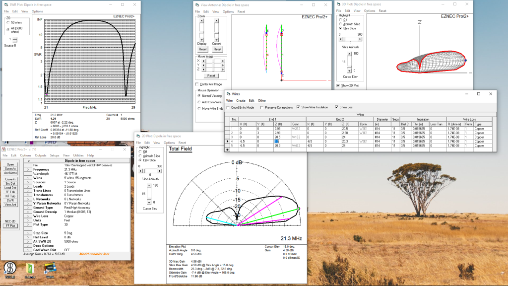
Now to form a vertical beam I use the same trap for 10m and cut matching parasitic wires. I have the separation between the elements at .13 wavelength at 15m but fix that for both 15m and 10m. This promises about 4dbi gain in the forward direction. Changing direction is super simple in that the parasitic element only needs to be relocated with no radials to contend with. Here is some modeling of this antenna on 15m:

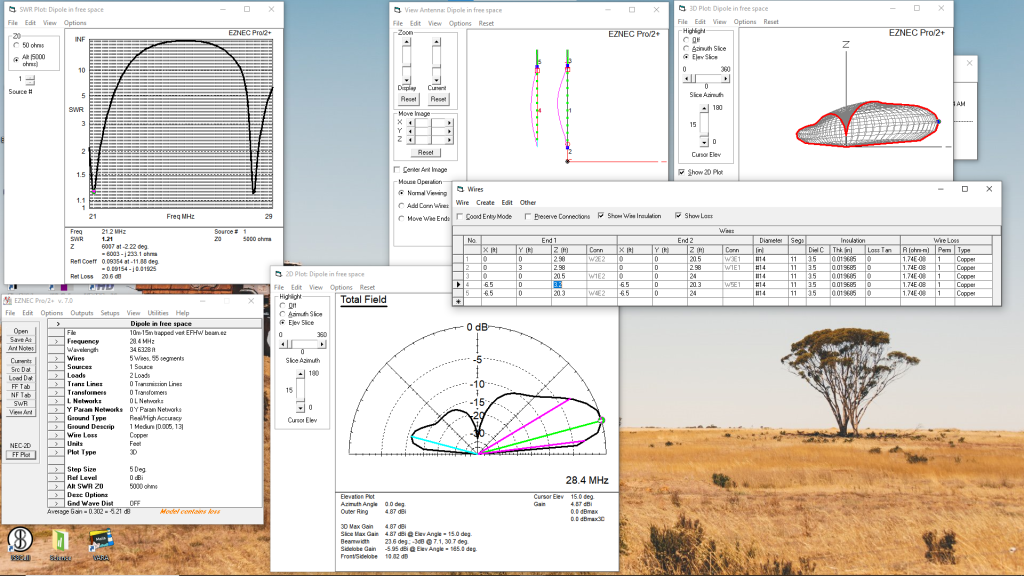
Here is the predicted performance on 10m:

This antenna shows some nice low angle gain which will be handy for DX. I recently tested the 15m mono and version and certainly noticed the directionality. I’ll start working on a trap for this and hopefully try out this weekend.

Antenna Maintenance Complete

Antenna weather in South Texas today. Sunny, 86°F with a slight breeze. Took the opportunity to do much needed maintenance on the S9V31 radial field. Upon inspection this morning I noticed at least six radials were not connected. I basically spliced in some wire or added new ring terminals to reconnect.I also took the opportunity to add two new long radials. These are at least 60 feet long. I also replaced a section of feed line and waterproofed the connections. These changes and repairs really perked up 20m. I had noticed that the tuner would find a match but the SWR was much higher than what I was used to. Happy to have my main HF antenna back in top shape.

I also took out an old favorite…the end fed half wave antenna setup as a vertical on 20m. Will play around with this today as well and compare to the S9V31.

Return of the S9V31 Vertical

The wind event late last week was not as severe as predicted. It was very breezy but the 50mph gusts did not materialize. I left town for the weekend and left the S9 vertical on the ground. Today is my first day of Christmas vacation so I went out this morning to set the S9 back up thinking it would be fairly straightforward. Well my motto “nothing is ever easy” proved true this morning.

First up was fixing a couple of pole segments that were slipping. I extended the tubes and re-seated a couple of hose clamps for those segments.

I then went over to the radial plate and checked the connections. I found that there were about 8 ground radials that were not connected to the ring terminals anymore! It looks like they had been pulled out of the terminal connections. I found the ends on average about 3 inches away from the connector. I suspect that i did not leave enough slack in the wire when I laid out and pinned down the radials. As the grass grew over them it must have pulled them away from the radial plate pulling several out of their connectors.

To repair these I replaced the ring connectors and added some short splices of wire to the ends remaining. The Bernzomatic portable soldering iron came in real handy in its first field use.

I made two additional changes to the setup. The small terminal box was connected to the 1:1 choke using a small coax patch cable. I replaced this with a PL-259 male-male adapter. This shortened the connected and provided some rigidity. I also replaced the braided ground strap forming the ground connection to the coax with copper strap.

Everything tested out good and so am now doing some testing. Made a few domestic SSB contacts with good signal reports on 20m.
The Alpha Antenna S9v31 is On the Air

After a full year of experimentation with vertical antennas I finally deployed the Alpha Antennas S9v31 antenna. It was a perfect day here for it as well. Mid 80’s with very little wind. A bit muggy for the work on the radial field but otherwise just a beautiful day in South Texas!

First up was finishing up the radial field. I set out the radial plate with 20 radials with lengths that vary from about 10 feet to just over 25 feet. The back breaking job was installing the lawn staples to hold them down. Tedious but straightforward. The yard was freshly mowed and I had tested three long radials and found no issues with the mower. Here is the finished radials:

Next I removed the 20m vertical element and finally lowered the SOTAbeams travel mast. This mast took a great deal of abuse over the past year or so and all told is still in serviceable shape. I highly recommend this mast!

The setup of the S9 was really simple. The mast is extended on the ground and a set of clips installed at each section joint to prevent collapse. The radiating wire is inside the mast. Once extended it is walked up and I mounted it onto the same aluminum angle I used with the travel mast. The hook ups remained the same with the junction box and ugly balance used before.

Here is the finished product:

I am running WSPR on this now so will report on performance after I collect some additional data.

A Quick Radial Experiment

I added about 12 feet to two of the 40m quarter wave radials, trimmed the ends so there is bare copper and dropped then into the resaca in the backyard. For those not familiar with the word “resaca”, it is a type of oxbow lake which in my case was a channel of the Rio Grande River that was cut off from the river and forms no inlet or outlet. The water is fresh but somewhat brackish.

The result appears to be minor. SWR dropped to 1:1 but not sure if it is because of the longer wires or the contact with water.

Practical Application of Soil Measurement Data

Anyone interested in ground radials, ground mounted verticals and even elevated radial verticals should visit Larry Severns, N6LF, website. he has done extenstive research om the subject and has published his results in QST and QEX with many of these articles available on the website. His article ” Experimental Determination of Ground System Performance for HF Verticals Part 4 How Many Radials Does My Vertical Really Need?” was originally published in QEX May/June 2009 edition. The following graph was taked from this paper:

2017-10-09_11-40-24

This graph shows the change of signal improvement on a 1/4 wave vertical with 1/4 wave ground radials under different ground conditions. The impact of this graph is that when the ground is “good”, adding more radials results in small signal improvement vs when using a “poor” ground. I can expect a .2dB improvement if I double my radials from 8 to 16. If I double again to 32 radials my signal improvement would be only around .5dB.

There is a real economic benefit to having good soil as in general fewer radials are needed because the ground losses are less than when over poor soil.

Measuring Ground Properties at the QTH

Rudy Severns, N6LF, published a paper entitled “Measurement of Soil Electrical Parameters at HF” where he shows several methods of measuring the electrical properties of soil. I built an OWL probe using his directions made from two parallel 1/2″ aluminum rods spaced 4″ apart and 11″ long.

20171008_004844437_iOS

Once assembled I measured the capacitance of the probe with the L/C capacitance meter which measured it to be 6.16 pF. I inserted the probe in the ground around my vertical antenna then connected the RigExpert AA-230 Zoom and measured impedance at several frequency points in the HF bands. The Resistance and Reactance are used to calculate the soil conductivity and Er values. Here is a graph of the results:

2017-10-07_20-00-54

The data collected at this one point confirms that the soil in South Texas is quite good in terms of conductivity and Er. I will use these values when modeling antennas with EZNEC. This was the initial test and I will likely try some other areas of the backyard and see how much it varies and whether the data is consistent